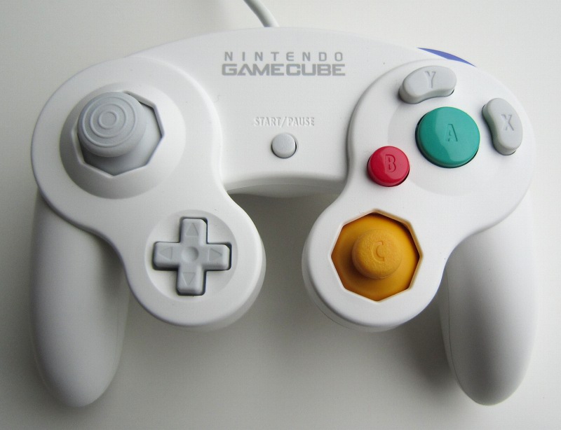
Does this mean I should plug, say, the blue wire from the controller and a wire from the 3. But then apparently I'm also supposed to connect a 1k (or higher) resistor between the data and 3.3v. In this tutorial I will show 2 different types of Goomwave systems. It uses the Arduino IDE to upload sketches either to a normal Arduino or an ATtiny85 to read the GameCube controller signal and perform LED actions based off of those inputs. I read that I need 3.3v going into the blue wire, and I need the red data wire to connect to the Arduino's pin 2 to send and receive data. Goomwave is an open-source, customizable, reactive LED system for use with GameCube controllers.

The only resistors I have are 330 and 10k I attached a 10k although I'm still slightly confused about where it needs to go. That should be OK, since I'm pretty sure all the Nintendo controllers have the same color wires. And I can eventually re-attach the wires if I really need to (which isn't likely).Īs for getting it to work, well, I can't exactly see which wire goes to which pin in the plug, so I basically only have colors to work with. on the top of the wii are 4 ports for gamecube controllers. I do have an excuse though: The cable casing already had an opening ripped in it, so it technically wasn't a perfectly good controller. yes (, but you need a gamecube controller and a memory card to play the game (nintendont can emulate these things)) SablePlays said: is it possible to attach a gamecube controller to a family edition wii without soldering the ports. Too late I already have stripped the wires for the actual controller. But I have no formal education in electronics, so.
#GAMECUBE CONTROLLER PORT CNC CODE#
The code I was trying to run was this, which I tried to use after (I think) installing the HID project by the same guy, but I'm a little unsure about how one goes about using the stuff from GitHub.Īlso, the schematic on that page is very confusing, because I don't understand any reason why I would need to use a logic level converter if I'm using a pull-up resistor. My controller is a purple official Nintendo controller DOL-003 if that's of any help to anyone. I'm fairly certain yellow is supposed to go to a 5v supply from the Arduino, and I think the green and white are ground, but the red, blue, orange, and where to connect a resistor are a mystery to me.


Well I actually disconnected it all from the breadboard (after assuming it was not connected right), and to be honest I can't even remember how I had come to the conclusion to connect it that way in the first place, because the instructions I found each told a different way to connect the wires, presumably due to wire colors not being the same with all controllers.


 0 kommentar(er)
